Simulate a design with Modelsim
This presentasion describes the use of the Modelsim environment for design and simulation of a Verilog module. The module to be implemented has one 8-line input and one output. The output is set to 1 when the hundreds' figure of the unsigned input number is 2.
Create a new Modelsim project
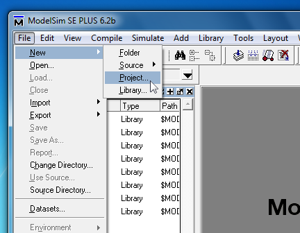
File -> New -> Project
Select project's location and name
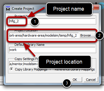
Chose a name for the project and set its location. Click OK.
Add file to the project
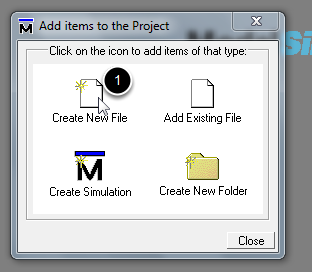
Click Create New File.
Create a Verilog source file
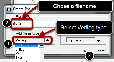
Select the type of file to Verilog. Chose a filename (if the type was already selected to verilog do not add any extension). Click OK.
Close Add items to the Project window
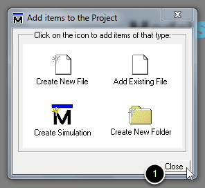
Click Close
Open the newly added source file for editing
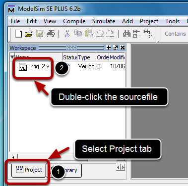
Select the Project tab (if not visible activate it from menu View -> Workspace). Double-click the sourcefile to open it for editing.
Edit the sourcefile
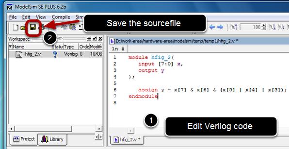
Edit the Verilog code as depicted in the image. Save the sourcefile.
Important: It is essential to asve the source code before compiling it!
Compile the Verilog description
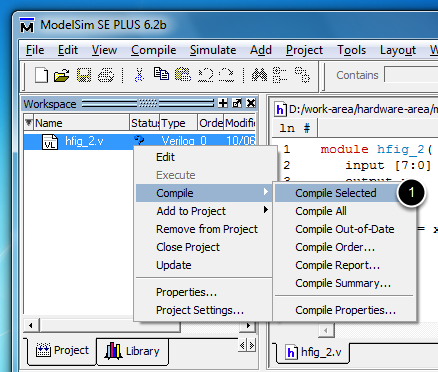
Right-click the sourcefile in the Project tab and select Compile -> Compile Selected submenu.
Check correct compilation in the Transcript window
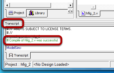
If an error occured, double click the error line in the Transcript window to open a compilation report indicating the possible cause of error. If no error occured the succesfull compilation is notified in the Transcript window.
Start the simulation
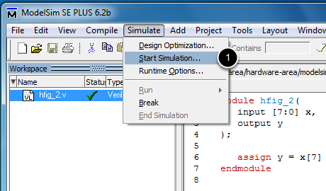
Click on Simulate -> Start Simulation... submenu.
Modify the optimization options
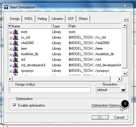
Click the Optimization Options button.
Select full debug mode
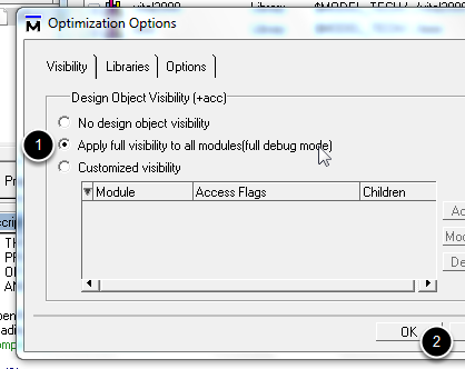
Select Apply full visibility to all modules(full debug mode) option. Click OK.
Select the module to simulate
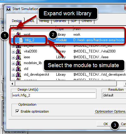
Expand work library (in the Design tab). Select the module to simulate (the items in the work library have the names of the modules not the filenames of the sourcefiles Observation: Name a sourcefile the same as the module it implements). Click OK.
Simulation layout
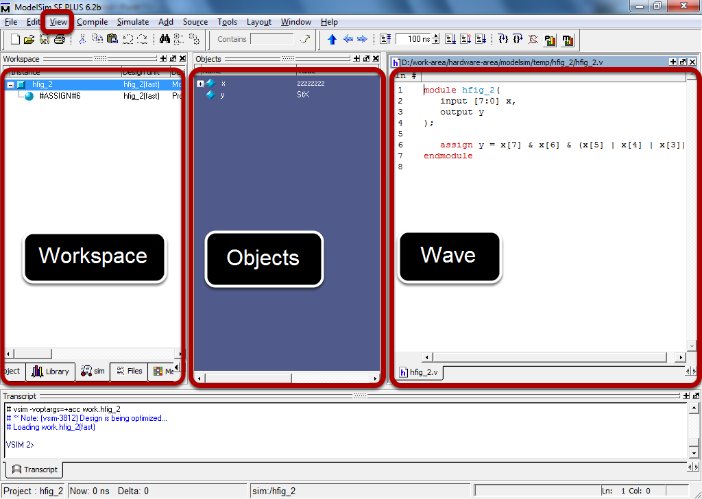
The following windows are required for simulating the design: Workspace (opened from View -> Workspace menu), Objects (opened from View -> Objects) and Wave (opened from View -> Wave).
Create waveforms for inputs
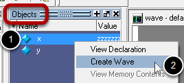
For all the inputs (in our case a single input, x, on 8 bits) create a waveform by right-clicking the signale name in the object window and selecting the Create Wave menu.
Format each waveform individually
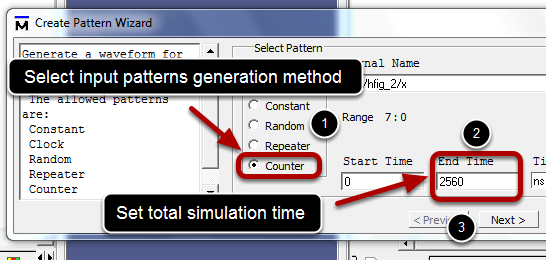
Generate the waveform accordingly to the design being simulated. For this case, all input configurations from 0 to 255 are to be set for the input x. Each configuration will be active on the input line for 10 ns. Since there are exactly 256 numbers from 0 to 255, and each of them will be active for 10 ns, the entire simulation will need to run for 2560 ns. The input patterns need to be generated in this case by a counter because all input configurations from 0 to 255 need to be applied to the input x, thus select Counter. Enter the length of the simulation. Click Next.
Format each wave individually (continued)
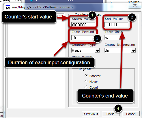
For the counter pattern generation the initial value and the final value of the counter are required. In our case set the start value to the configuration of 0 (00000000) and the End value to the configuration of 255 (11111111). Also sets the time period being the time each input number is active on the x line. For our case set the Time Period to 10. Click Finish.
Add outputs to the waveform window
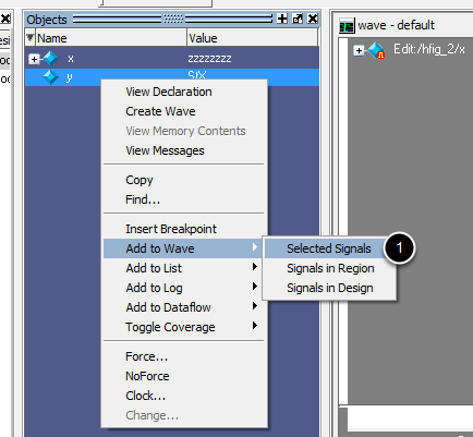
For each output in the design add it to the wave window. In this case add output y to the wave window by right-clicking it in the Object window and selecting Add to Wave -> Selected Signal
Zoom out/in the waveform
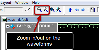
Zoom in/out for adequately viewing of the waveforms.
Adjust radix for the signals in the wave window
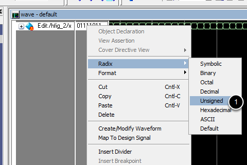
For each signal needing radix modification, right-click it in the Wave window and select the correct radix from the Radix submenu. In our case, because the input number is an unsigned, select signal x, right-click it and chose Radix -> Unsigned.
Roll simulation timeline all the way to the start point
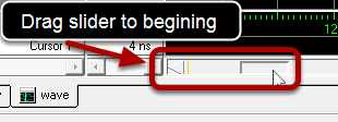
Drag the timeline slider to the begining
Run simulation
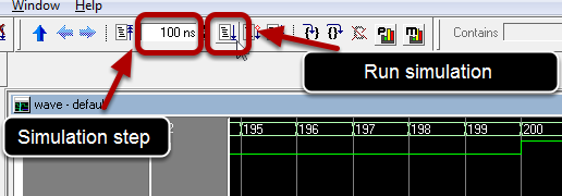
Run the simulation repeatedly for all input configurations. The simulation step, as seen in this image is 100 ns, thus, at least 6 runs are required to cover all 60 input numbers.
Inspect outputs' correctness

A cursor is positioned when clicking the wave window. The current value of all the signals are displayed in the values region. Inspect the outputs for all relevant input configurations by scrolling the timeline
Stop simulation
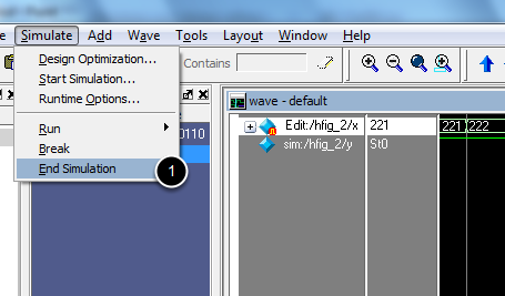
Stop the simulation from menu Simulate -> End Simulation. Important: Before modifying and recompiling a design the simulation need to be stoped!
Add additional sourcefiles to the design
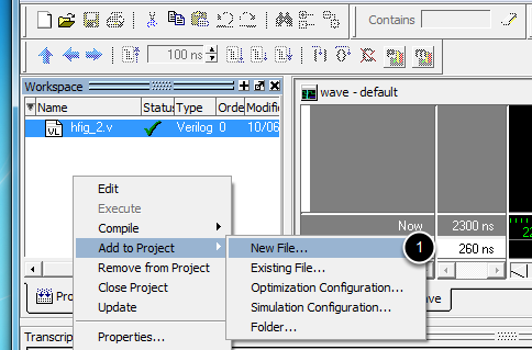
In the Project tab of the Workspace window right-click an empty spot and select Add to Project -> New File... The same considerations apply as in step 4.