Quartus Design with Block Diagram
Define components using the block diagram (Quartus version used 7.2)
Creater a new block diagram
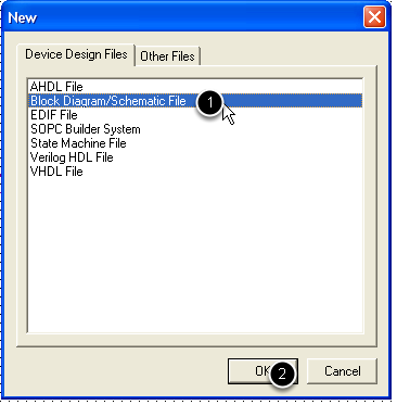
Select the File->New menu, and the Block Diagram/Schematic File option.
Save the newly opened schematic file
If the diagram is for the top-level entity, name it the same as the project.
Adding a component to the schematic
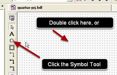
Double click the schematic working space (or click the Symbol Tool)
selecting the component to be added
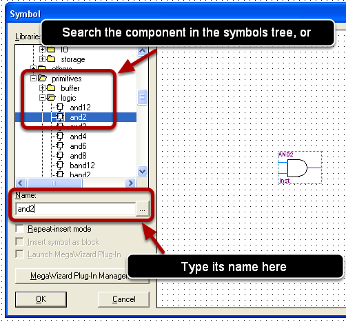
Either type the component's name into the Name field, or search it in the symbols tree.
Place the component on the schematic working space
Click the inserting position
Wire the components
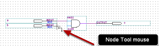
Place the mouse near a pin until the cursor change into the Node Tool
Wire the components (continue)
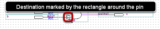
With the mouse as the Node Tool, click, and drag the connection to its destination.
Avoid "unclean" connections
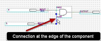
Avoid using connections at the edge of a component
Avoid unintended nodes
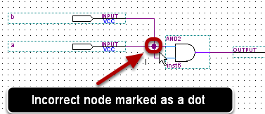
Avoid nodes resulting from unwanted/unintended connections. Nodes are usually marked as dots on connectors.
Compile the design
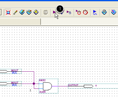
Click the Start Compilation button
Solve compilatin errors
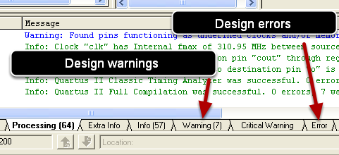
Resolve the errors of the design marked in the Messages frame. Most of the warnings can be ignored.