Quartus Design Simulation
Simulating a quartus project (Quartus version used 7.2)
Compile the design
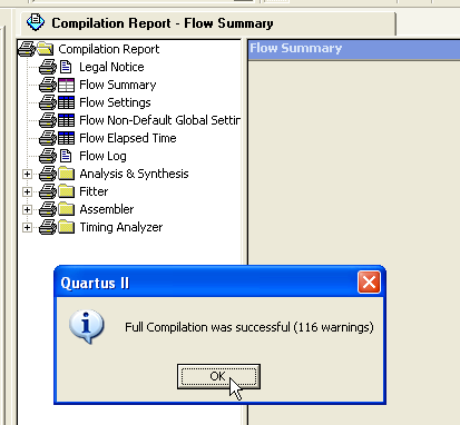
Make sure all design errors are solved before continuing.
Insert a vector waveform file
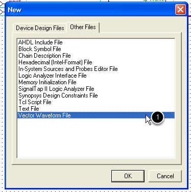
Click the File -> New menu, and select from the Other Files tab the Vector Waveform File option.
Save the waveform file
For simulating the top-level entity, name the waveform file the same as the project.
Set the maximum simulation duration.
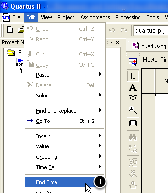
Set the ending simulation time from the menu Edit -> End Time
Set the maximum simulation duration (continue).
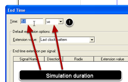
Enter the maximum simulation time
Insert the signals observed during the simulation
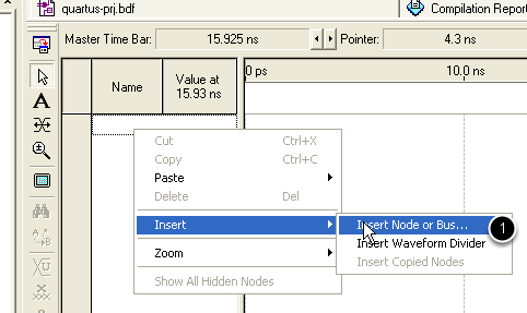
Right click in the first column of the waveform file and select Inser -> Insert Node or Bus menu.
Insert the signals observed during the simulation (continue)
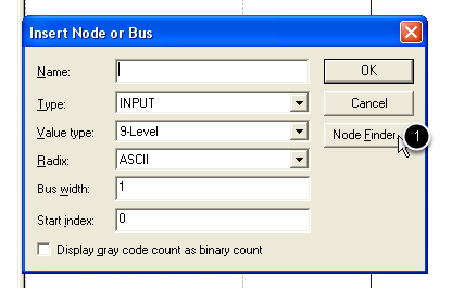
Click the Node Finder button on the Insert Node or Bus window
Insert the signals observed during the simulation (continue)
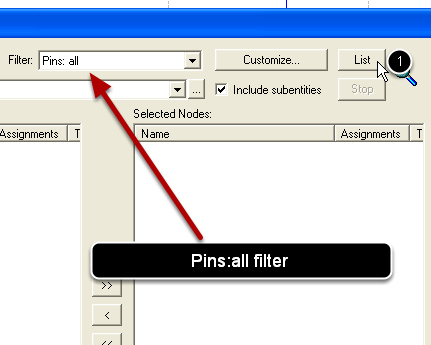
List all pins in the design (the design must be first compiled) by clicking the List button. Make sure the Pins:all filter is selected.
Insert the signals observed during the simulation (continue)
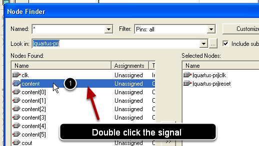
Double click all the signals you are interested in simulating to add them to the Selected Nodes colum
Insert the signals observed during the simulation (continue)
Press Ok button of the Node Finder window.
Press Ok button of the Insert Node or Bus window.
Create the waveforms for inputs
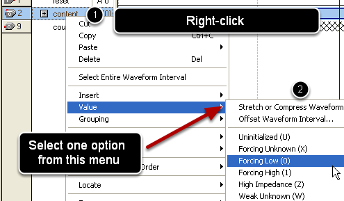
Create the waveform for an input signals by right-clicking on it and selecting one option from the Value menu. (logic low - implicit; logic high, clock, random, ...)
Simulate the design
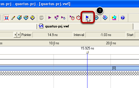
After constructing waveforms for each of the input signals, the simulation is started usin the Start Simulation button.
Analyze the simulation results
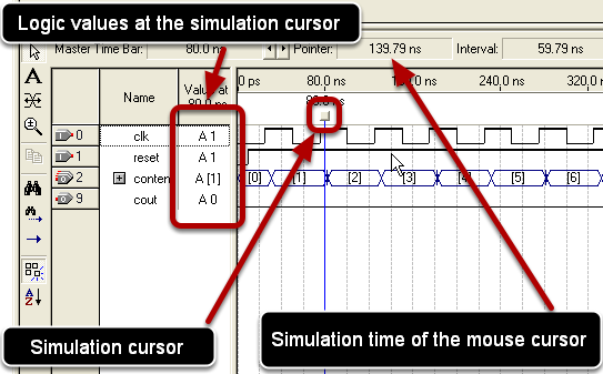
Automatically, the simulation report is opened, containing the waveform of all signals (input and output). The cursor can be used to view the logic levels at a particular moment of time.