Quartus Project Pins Assignment
Assign pins on the DE2 board to a Quartus project
Compile the Quartus project
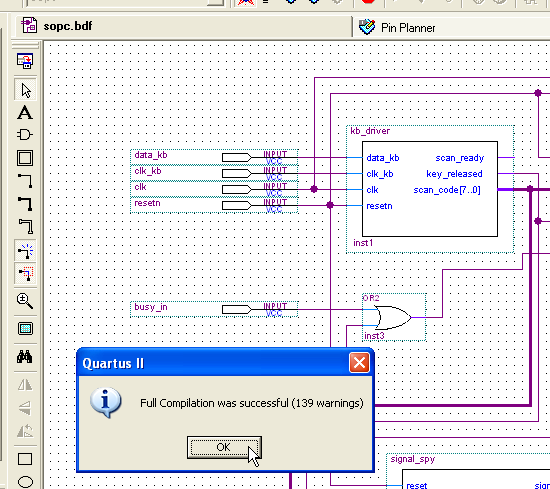
Before assigning pins, make sure the Quartus project compiles sucessfully (or almost sucessfully).
Open the Pin Planner
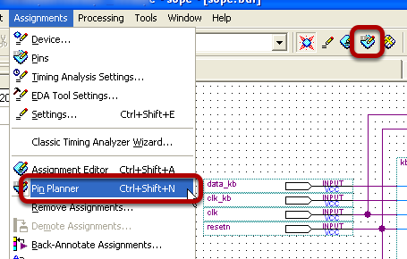
Either use the Assignments menu, or the Pin Planner button on the toolbar
Open the DE2 pin assignments table
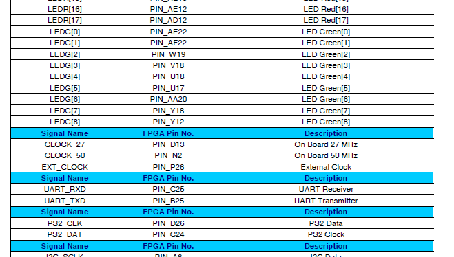
The document, entitled "Altera DE2 Board Pin Table", can be accessible from here, or can be used online. It contains references of each DE2 configurable pin, and it's function. For example, the 50MHz clock signal, as depicted in the figure, is connected to the DE2's PIN_N2 pin. The pins connected to the green leds are also depicted in the figure.
Assign pins
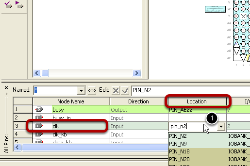
In the Pin Planner tool, for each and every port of the Quartus design (input, output or bidirectional), a DE2 pin need to be associated, as shown in the figure. For the CLK port, the 50 MHz clock signal is selected, and in consequence, in the Location column of the clkinput line, after double clicking, the PIN_N2 name is entered (typing only the suffix: N2, works as well). The process is repeated for all pins
Configuring the unused pins
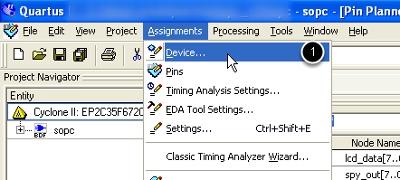
Important: This step is mandatory in order to avoid deteorating the DE2 boards. Set all the unused pins as inpuit tri-state, as shown in the figure. For this open the Assignments -> Device menu.
Configuring the unused pins cont'd
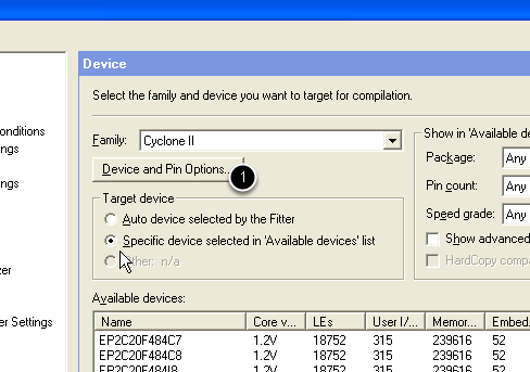
Click the Device and Pin Options button
Configuring the unused pins

In the Unused Pins tab, set all the unused pins as inpuit tri-state.